
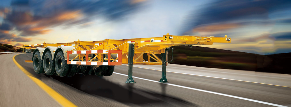
CATEGORIES


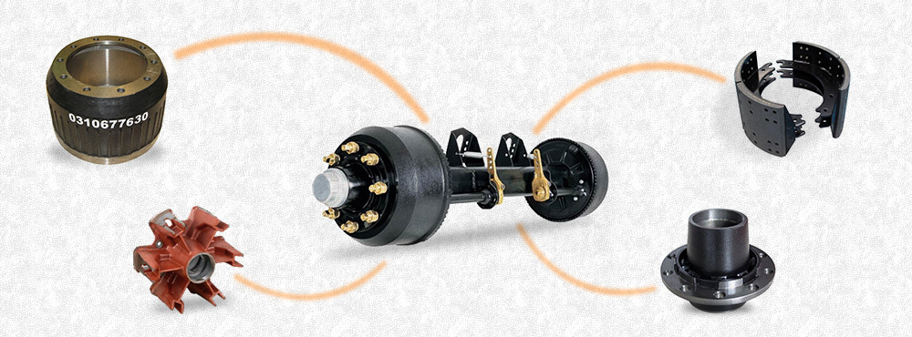
BRAKE DRUM
WONDEE Tell You the Automotive Brake Types
Various types and combinations of types of brakes are employed to provide safe braking on current vehicle designs. Each vehicle must, by law, have two independent brake systems for safety. The mainbraking system is hydraulically operated and is called the service brake system. The secondary or parking brake system is mechanically operated. It is designed to hold the vehicle on a 30% (16.7°) slope, and it must be capable of stopping the vehicle if the service brake system should fail.
The automotive brake systems are divided into three types of service brake combinations: drum brakes, disc brakes, and disc-drum combinations. All three combinations of brake systems are in production. Automotive drum brakes may be either the dual-servo type or the leading-trailing shoe type while some trucks use the double leading shoe type. Disc brakes are divided into two main types: the fixed caliper and the floating caliper design. Disc-drum combinations employ nearly every possiblecombination of disc and drum brake types.
Drum Brake Design
Drum brakes use an internal expanding brake shoe with the lining attached, working within the confines of a rotating brake surface called a brake drum. Typical drum brake parts are shown in Figure 6-3. The brake surface by a hydraulic cylinder that is referred to as a wheel cylinder. The brake drum is fastened between the wheel-tire assembly and the hub assembly on the nondriving wheels of the vehicle. Fluid pressure from the master cylinder supplies fluid to the wheel cylinders causing them to expand. The expansion of the wheel cylinder through mechanical linkage forces the brake linings into contact with the rotating brake drum to provide braking action.
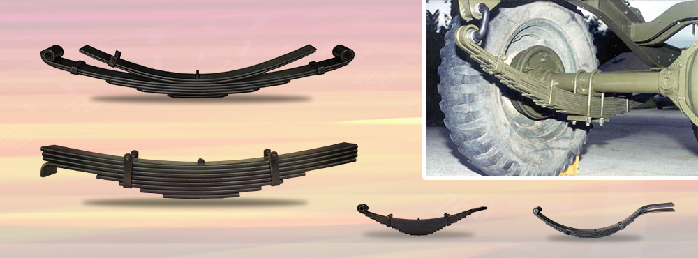
The many components within the wheel brake are used to support, apply, adjust, release, and transfer the braking torque to other suspension members. A backing plate is attached to the wheel spindle or axle housing to provide support for the brake shoes and to transfer torque from the brake shoes to the suspension member. As the brake linings come into contact with the rotating brake drum, they attempt to rotate in the same direction as the rotating wheel. The brake shoes, with the linings attached, are prevented from rotating by the anchor which is securely attached to the backing plate. The wheel cylinder is also fastened to the backing plate and this provides a secure mounting location. On dual-servo brake systems, a screw and adjustment placed between the two brake shoes, opposite the wheel cylinder, provides a means for adjustment to compensate for brake wear. This adjuster may be automatic (self-adjuster) or manual. Nearly all dual-servo brake systems used automatic adjuster. The automatic adjuster may not be used on vehicles employing heavy-duty brakes, such as police cars or trucks. The automatic adjuster makes use of the slight rotation while backing the vehicle to make the automatic adjustment.
Leading-trailing (Figure 6-4) and double-leading brake shoe arrangements use a cam or screw to manually adjust for lining wear. One exception is a leading-trailing configuration used on the rear of some passenger vehicles that adjusts when the parking brake is applied and released as shown in Figure 6-5. These types cannot use an automatic adjustment as used in the dual-servo brake because two anchor points are used to prevent even the slight rotation of the brake shoes that is needed to actuate automatic adjusters.The dual-servo brake shoes are held to the backing plate with pins, hold-down springs, and retainers. These parts are pictured with other brake parts in Figure 6-6. These parts allow the brake shoes to move when the brakes are applied. The additional fluid that has been forced into the wheel cylinder to expand the brake shoes and linings must be returned to the master cylinder to allow the brakes to release. The return springs provide the force necessary to pull the shoes away from the drum and to contract the wheel cylinder. This action will force the surplus fluid from the wheel cylinder and return it to the master cylinder reservoir. The return springs may be used in a number of different arrangements, although their purpose, that of contracting the expanded shoes, is the same.
Drum Brake Operation
Self-energizing drum brakes are the most commonly used brake design. A self-energizing brake is one in which the drum rotation increases the brake shoe application force supplied by the wheel cylinder. Conversely a non-self-energizing brake design would be of the type in which drum rotation decreases the application force of the wheel cylinder. Figure 6-7 compares self-energizing with non-self-energizing brake action with a trailer that comes off from a hitch. Some wheel brakes incorporate one brake shoe that is self-energizing and a second shoe that is non-self-energizing. Other designs have both brake shoes self-energized or neither self-energized when the wheel is rotated forward.
Dual-Servo Brake Design
The most popular drum brake design currently in use employs self-energization. In this brake the front brake shoe (primary shoe) is applied by the wheel cylinder. The force of the primary shoe, being pulled by the drum, is used to apply the rear (secondary) shoe. This type of brake is referred to as a dual-servo design and it is self-energized during both forward and rearward wheel rotation.
Self-energization occurs any time the drum rotates from the point of force application (wheel cylinder end) toward the fixed or anchored end of the shoe. In drum brakes as shown in Figure 6-8 the portion of the shoe that is forced into the drum is referred to as the toe while the end of the shoe near the anchor is termed the heel. If a point on the drum rotates from the toe to the heel, the shoe is a leading shoe. If rotation is from the heal to the toe, the shoe is a trailing shoe.
The self-energizing force on any brake is dependent upon a number of design limitations. These limitations include the location of the anchor pin, the arc formed by the brake lining, the location of the lining on the shoe, and the coefficient of friction of the lining. The anchor pin location and coefficient of friction can be selected and designed so the brake will lock and not release until the drum is turned opposite to the direction of rotation. The locking effect of the self-energizing force will increase as the anchor position is selected closer to the center of the backing plate and as the coefficient of friction of the lining is increased. The location of the lining on the shoe and the arc of the lining will modify the self-energizing force. If the lining arc exceeds approximately 120°of the brake surface, as shown in Figure 6-9, the energizing force tends to increase near the ends of the linings to the extent that brake squeal may develop. As the lining location on the shoe is moved from the toe toward the heel of the shoe, the self-energizing force of the shoe is decreased. If the lining is positioned too near the toe, the energizing force is greatly increased and the brake will tend to grab.
Advantages and Disadvantages of Dual-Servo Brakes
Because of its efficient self-energizing system, the dual-servo brake requires less operator effort to be made smaller than those on other types of brakes. This dual-servo system, because it employs a double-ended wheel cylinder and a moveable link between the two shoes, provides self-energized braking in both the forward and rearward directions.
The dual-servo brake, as shown in Figure 6-3, is not without its drawbacks. The secondary shoe application results from the applied forces of the primary shoe. Anytime that affects the coefficient of friction of either lining will alter brake performance drastically. This brake design suffers more from brake fade than the other brake designs as a result of the loss in coefficient of friction due to increased temperatures. Water on brake linings also changes the coefficient of friction. When one brake is wet, on dual-servo brakes, violent pull will occur as the brakes are applied. This system, due to self-energizing, relies on the secondary shoe to provide approximately 75% of the total braking effort.
Alternative Brake Designs
Other designs of drum brakes (including the leading-trailing, double-leading, and double-trailing types) do not rely on the force of one shoe to apply the other shoe as in the dual-servo brake. This feature allows each brake shoe and lining to function independently of the other within each wheel brake. Because of their independent action, the effects of fade and dampness are not as great as in the case of dual-servo brakes. This results in more predictable braking action under adverse driving conditions.
The independent action of each brake shoe using the shoe arrangements above produces less stopping power for the same pedal force when compared to the dual-servo brake. Consequently, the wheel cylinder and brake diameters must be made large enough to provide the greater required braking power with a reasonable amount of driver effort.
The double-leading and double-trailing brakes require two one-ended wheel cylinders to provide the required operating characteristics. The double-leading brake has two self-energized shoes operating independently of each other in a forward direction. In a rearward direction the shoes are not self-energized and so braking will require considerably more pedal force. The double-trailing brake design operates without self-energizing action in the forward direction in the same way as the double-leading brake does in the reverse direction. Because these brakes do not have a self-energization force the braking action is directly proportional to the input pedal force. Due to a forward weight transfer of the vehicle during a stop, the front brakes require a reduced or at least a constant braking power to prevent premature rear wheel lockup in a hard stop. Brake proportioning in some lightweight vehicles with disc-drum brakes uses a leading-trailing rear brake shoe configuration used on the front in conjunction with the double-trailing brakes used in the rear has, in obsolete brake systems, provided the required brake proportioning.
Disc Brakes
Disc brakes employ a brake disc that rotates with the wheel. The brake disc is usually referred to as a brake rotor. A hydraulically operated caliper is used to force the lining friction material against the braking surface of the rotor for stopping wheel rotation. The brake shoes fit inside the caliper housing to prevent end movement of the shoes when they are being forced into contact with the rotating brake disc.
Disc brake shoes move perpendicular to the face of the brake rotor to provide a clamping action on the rotor to slow the vehicle motion. The clamping action of the shoes against the rotor produces a force that is proportional to the driver pedal effort.
Disc Brake Design
Disc brakes are made in two basic configurations. The two types differ mainly in the number of pistons and the type of mounting used for the caliper. This is required because different application methods are used for the out-board shoe. The floating caliper design uses an adapter bracket to or cast as a part of the steering knuckle. The caliper is mounted on this bracket. This allows the caliper to slide in and out with little resistance, while still preventing the caliper from rotating with the rotor as the brakes are applied. The piston forces the inboard shoe or pad into contact with the inboard side of the rotor. At the same time the reaction force from the piston moves the caliper housing inward, bringing the outboard shoe or pad into contact with the outboard side of the rotor. This action-reaction force of the caliper provides an equal force to both the inboard and outboard shoes to provide the clamping action of the linings on the rotor that is necessary to produce the required stopping power.
The floating caliper type of disc brake, as shown in Figure 6-11, usually employs a single piston when used on passenger vehicles. Heavier vehicle applications may use two or more pistons in the inboard side of the caliper to increase the applied force on the lining and to create more application points along the length of the shoe for more even lining wear.
The fixed caliper type of disc brake uses a securely mounted caliper, centered over the brake rotor with application pistons for each brake shoe. The caliper has an adapter plate mounted to the steering knuckle. The caliper is mounted on the plate in position over the brake disc. The secondary purpose of the adapter is to provide a link that will allow for some movement of delection is required to prevent damage to the caliper and rotor during brake application.
The fixed caliper brake has two or more apply pistons. A minimum of one piston for each brake shoe is required. Many fixed caliper brakes use more than two pistons. Because the caliper movement is not used to equalize the application force on each side of the rotor, as in the floating caliper design, the separate pistons applying each shoe are required to equalize the application force on each side of the rotor. Equal application force prevents the rotor from being pushed to one side as the brakes are being applied. The use of more than one piston per brake shoe makes it possible to use a longer, more slender caliper. With more application points per shoe there can be greater total application force for each shoe. Drawbacks of the multiple piston caliper incude an increased machining cost and the increased number of contact points provide more paths for heat to travel into the brake fluid more rapidly, which in turn can lead to earlier brake fade.
Disc Brake Operation
Disc brakes offer better heat dissipation than drum brakes because they have direct contact with the moving air that surrounds the brake. The direct air cooling shortens the cooling cycle to provide quick recovery if the linings are heated to a point where fade could occur. The brake rotor will quickly free itself of any water and foreign matter from its braking surface during rotation. This occurs as the centrifugal force throws the contaminants outward, away from the vertical brake surface.
Disc brake linings are not self-energized because their movement is perpendicular to the disc rotation when they are being applied. This lack of self-energization reduces the tendency for adverse braking that occurs in self-energized brakes. This is especially noticeable when the brakes are overheated. Because the linings are not self-energizing, a greater application force is necessary to provide the required braking action with moderate driver pedal effort. The high application force on the rotor is achieved by using large diameter hydraulic cylinders and , most often, included the use of a power assist to increase the force produced by the brake pedal. Because the disc brake calipers have larger diameter pistons than those used in drum brakes, the disc brake requires a larger quantity of brake fluid to move the pistons an equal distance. The service brake pedal must travel farther to provide this increased volume of brake fluid. The requirement for increased pedal travel may be overcome by using a larger diameter master cylinder. This, in turn, will decrease the mechanical advantage of the brake system. A power brake booster is then required to increase the mechanical advantage sufficiently to allow stops with a reasonable brake pedal force.
The brake caliper operates much like a vise as the brakes are being applied. The clamping action of the caliper on the rotor places a force on the caliper that tries to make the caliper spread apart. Any distortion of the caliper will result in a greater pedal travel and a "spongy" pedal feel. For this reason most domestic vehicles use calipers made of cast iron. Calipers on some lightweight vehicles are made of aluminum to lessen the weight of the brake components at the wheel.
Other types of parking brakes have been used in the past. One type that was popular was fitted into a drum connected to the transmission output shaft. Setting the parking brake would then prevent rotation of the drive-shaft to prevent vehicle movement. Similar drive-shaft parking brakes are sometimes used on medium-size trucks.


